
[Part 2 of our exploration of drone-lifted antennas for Ham Radio use. See last week’s article “Goodbye Radio Towers, Hello Drones.”]
Drone s– particularly used for lifting things – is an incredibly cool technology.
Already, commercially available fishing drones operating up to with up to 8-pound loads are available. Not cheap, but out there. $1,500 class and up. Dandy if you like surf fishing and you’re not right off the end of a beachfront runway. And no worries at the end of Princess Juliana International Airport in St. Maarten anyway – too many bathers and not enough fish. (Jeez, how’d we get lost over there?)
Back to point: Radio Towers are big, expensive, want to fall over. Yet virtually all ham radio ops want a taller one. The higher an antenna is, the better it works, generally speaking.
Drones can’t replace all radio towers, but they can replace a lot of ‘em. Towers have higher ultimate wind survivability, for example, than drones. But the Cost/Benefit is there for drones in many instances.
We think it’s only a matter of time until someone (besides us) begins offering game-changing drone-lifted high performance directional HF radio arrays for the ham radio market.
Drone Cost-Benefit Breakthrough
Conventional ham radio enthusiasts are cost-limited in the height of antenna used. However, it’s axiomatic on the radio engineering end (though not the financial side) that there is no such thing as “too high” for an antenna. With the possible exception of NVIS (near vertical-incident skywave) applications. Price is another matter. That touches everyone.
Compared to a tethered drone, such as we described in last week’s article, radio towers are ungodly expensive. While the price point for a four or five drone lifting constellation could be in the $2,000 class, permanent radio towers of sorry losers. Let’s get specific.
I recently priced an 89-foot crank up tower to replace the 60-foot crank up tower here. The basic tower was $21,000 plus another (roughly) $1,000 in freight and delivery charges. Call that $22,000.
Permanent tower installation also means dirt work, steel work to weld up a base, plus pouring concrete in a precise way. Toss in another $5,000 for these. Running subtotal is now $27,000.
Then we will need the rotator ($1,500) and the antenna ($1,800) plus control cables for the rotator ($300+). Quickly, the cost of a basic tower at the 90 foot level? $30,600 – and that’s before hiring the labor to put it all together, assemble and test. Likely another $6,000 to $10,000 depending on location.
On top of this – if you don’t live in a Homeowner Association where tall permanent radio towers tend to be stillborn – you would also have permits, inspections, and approvals. Toss in a zoning variance depending on local terrain and view/sight lines of other property owners and complications spiral. Put some money aside for consulting engineers and legal counsel.
Time is another consideration. A five drone array (to lift a low-noise, quad antenna of lightweight materials, is easily envisioned arriving in a single packing box and being airborne in an hour, or less.
Being an older ham, the potential short lead-time of drones and their relative immunity to HOA regulators, means even on an equal-performance basis, they’d be clear winners.
We see a new world of ham radio deployment. A box with a number of drones inside, power source, a downloadable app to control your antenna constellation and specialized lightweight wires… Imagine it weighing less than 30 pounds from Amazon or Wal-Mart. Need that overnight? Want the 160-meter array, too?
For low power operators, QRP ops, you can “get by” with a two drone (Type 2) 120-foot tethered drone solution. Which could be configured either as the L (Marconi) or Zepp type. Where the two wire open feedline of the Zepp could carry power to the drone, as well as be the radiating element.
Insert Magic Here
Obviously, such a “neat idea” must have its flaws, too. Or it would likely be on the market already.
Let’s explore what the problems are and dig into some key design and “bring to market” issues.
- There power-density/RF interference engineering required. In configurations where you are mixing RF feedlines and power, the there’s some risk that the drone electronics could radiate (as part of the antenna) if RF isn’t decoupled from the antenna wires/feedline.
- We can borrow a solution from the SDR (software defined radio) world. There, power and radio energy are separated using a “Bias-T” approach. This provides “piggybacking” power and RF effectively.
- The “magic” is you’d need to ensure that the drone electronics are not adversely impacted by the radiated RF power.
- RF decoupling is straightforward, but this still increases total weight to be lifted by the drone. At lower ham radio HF frequencies, drone RF loading my not be an issue, however this would need to be determined experimentally.
- The weight of wire could be an issue, as well. While it sounds easy enough to say “Of course it will work!” we need to perform an engineering review.
Engineering Begins
A very rough (low data) first pass through the data offers that #28 AWG wire at 90-feet in length would weigh 77 grams. That’s a one-wire run, so we need to double weight estimates that are single conductor. Call it 160-grams for the wire up and the wire down just to put the drone into position.
The ampacity of #28 wire is reported at around 2.5 amps stabilizing at 40C in free air. We can see the weight problem more clearly now. Since each of the drone motors will be drawing about 3-amps (for a total of 12 amps) at (roughly) 4 volts. Call it 50 watts for rounding.
- A couple of answers appear in our “power paradox.” The first idea is to series connect the lift motors. Because while 12 amps at 4 volts is 50 watts of power, when we series the motors we can feed 12 volts up our tether line. Reducing the current to 4 amps.
Sadly, though, the drone electronics are all running on the lower voltage (4 volts) and we really need the GPS and radio for positioning. Not to mention the PWM control of the motors would need to be reworked. Still, this seriesing (is that a word?) of lift motors means that going heavier on the power wire size may not limit initial designs.
The Joy of Engineering
We have (in the first pass, or Blue Skying phase) enough data to believe a serious (measure everything) pass will lead to a workable design.
Since I’ve been on a world-class engineering team in my past (complete with a math consultant, lol) when we ran into design issues like this one, the first step is to go back and check all the design team’s assumptions.
As it turns out, the SWAG (*simple, wild-ass guess) of drone power was somewhat realistic. Research reveals that racing drones can gulp power at a fabulous 40-Amp rate!
Where assumptions were way off the rails was in wire weights involved. Turned out that the 77 grams for 90 feet of #28 AWG was my engineering initial engineering error. (This is interesting because you can see how personal bias limits good engineering!) The “77 grams per 90 feet” wire was insulated. Insulation not only takes up space, but it also weighs something to boot.
Which took me back to my early years in electronics. Where my pal (The Major) and I were ripping apart television transformers to salvage insulated antenna wire. Great wire too because it was covered with thin enamel providing almost no weight and good insulation as almost no weight.
As you’ll recall, we had (in the first pass phase) estimated our drone platform would likely need 12 Amps at 4 volts, or 50-watts worth of power.
To hone the answer to our first real engineering obstacle, we referred to two. For the weight of magnet wire, MWS includes the specs on their website at Copper-Magnet-Wire-Data.pdf (mwswire.com). But for the Ampacity of various wire sizes, we found these at Remington Copper Hook-Up Wire Ampacity Charts.pdf (remingtonindustries.com) where we immediately zeroed in on #18 magnet wire which (will warm to 90C open air under an 18 Amp load) looks like a good middle ground to begin with.
The weight of #18 magnet wire, says the MWS site is 4.92 pounds per thousand feet. Since we are planning only a simple 66-foot vertical for our initial flight test antenna, we will need 132 lineal feet of power wiring. This works out to 0.65 pounds or 295 grams.
At least on paper, we might have enough lift for the power wires and for a separate antenna conductor. We are at an engineering fork in the road, however. Three wires does not ensure decoupling due to capacitive linkage of RF into the power lines. Plus, two wires, not three, will give us more ultimate antenna height.
Project Engineering Data Search
This Second Design Iteration is where the rubber meets the road. This is where concept and design parameters harden. We try to lock what we will build and fly.
Further research to “harden up” out power and lift numbers came quickly.
“Potensic Smart Battery Specifications; Model: DSBT02A ; Capacity: 2,500 mAh ; Voltage: 7.2 V ; Energy: 18 Wh ; Working temperature: 32 Degree F – 104 Degree F; Weight 105 GM.”
Now we can work over our “seat-of-the-pants” and see what our real-world design will have to conform to. But it also became clear that eliminating battery weight at 105 grams could really add to the antenna length.
Let’s sharpen up power consumption. We suspect that with enough power we might get the 250 gram drone to lift what, 700 grams at least for a while?
As a practical matter, the platform we’re using (Potensic Atom SEs) are getting 25 minutes flight durations from an 18 Watt-hour battery.
Puking on Peukert?
Battery capacity shrinks based on rate of discharge. 18 Whrs of capacity at the 1-hour rate may be only 15 Whrs when delivered over 25 minutes.
That’s because Peukert (Wilhelm) discovered in 1897 that issues such as near-plate stratification was a time-based bit of electrochemistry.
As explained in Wikipedia on this point:
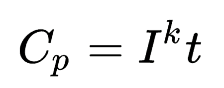
For a one-ampere discharge rate, Peukert’s law is often stated as:
Where
- Cp is the capacity at a one-ampere discharge rate, which must be expressed in ampere hours,
- I is the actual discharge current (i.e. current drawn from a load) in amperes,
- Then t is the actual time to discharge the battery, which must be expressed in hours.
- And the superscript Ik is the Peukert constant (dimensionless).
On our world-class engineering team, we turned this into an exponent to make the math work and reveal a highly accurate time to (settable) depth of discharge. But that doesn’t matter here since we’re wiring this up to ground power…but you need to keep “battery shrink at high discharge rates” in mind when designing drone systems.
The critical engineering point in this second pass through data is that the likely power loading was around 18 watts in a half-hour, suggests a 36-watt load divided between four motors based on a 7.2 volt battery pack.
Resizing Power and Antenna Wire
Power divided by Voltage will give us current, pointing to “normal flight current” as 36/7.2 or 5 Amps!
It may be less, down around 4 Amps because a) Peukert says battery capacity will less at higher discharge rates. And b) because terminal voltage under load (at the circuit board connectors will also sag somewhat at high loads. All reducing net watts available for lift.
This is great news!
Let’s go a tad overboard and plan for 8 amps at 7.5 volts (plus a little) to put total input power around 60 watts. Dandy. Normal flight plus some lift.
To this, we see in the Remington wire tables that #22 AWG magnet wire will give us 8 Amps. If we did need to push things along, the wire can be pressed to 90C at 10 Amps, or even 11 Amps at 105C but don’t burn your fingers.
As for the weight? The MWS data says #22 bare magnet wire rolls 1.94 pounds per thousand feet. So our measley 132 feet should only weigh 0.256 pounds or 116.1 gram.
Thanks to saving 105 grams (no battery in the drone now since it will be ground-powered) the possibility of a 160-meter vertical antenna comes into focus.
With an order in for the #22 AWG wire, we’re on hold until wire arrives and then this Ultra-Make will go back on the front burner.
Build Mapping
The very first step in a (crazy) project like this is to shop for the fastest, easiest components to build a POC (proof of concept) dronetenna.
Let’s use a block diagram to map what’s needed.
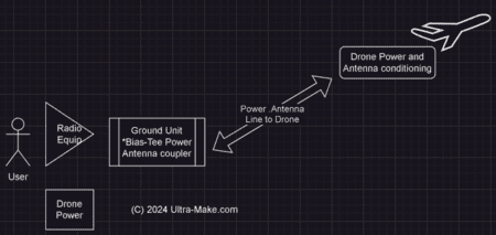
Now let’s talk about each part of this system view.
Radio Equipment
This is the easiest part. Multiple HF transceivers are on hand offering power levels from 1-watt in a small portable powered format for SSB voice and CW (Morse) on up to 1.3 kW output levels. Initially, I will be using a Kenwood TS-590S and begin at the 50-watt level.
Drone Ground Power Unit
This is also a simple task. The known battery for the Potensic Atom SE is 7.2 volts. As stated previously, this 18 WHr battery will provide less than 30 min. of flight time. Which leads to our estimation of 36-40 watts or stable flight and likely additional current loading at maximum lift capacity.
By using an adjustable 10-amp DC supply, we should have adequate power.
Antenna-Power Combiner
While there are plenty of circuits on the internet for Bias-Tee use, the idea here is to use the power line as a radiating element for the HF antenna.
To do this, I envision a simple DC power and radio feed arrangement something like this:
The drone Motor and electronics are upper right.
To make this as easy as possible for us, a number of on-hand parts from Amazon were selected:
- NOYITO DC LC Filter DC EMI Power Filter 0 to 50V 20A Filtering Board
- And for power? Adjustable DC Power Voltage Converter AC 110V-220V to DC 0-48V Module Switching Power Supply Digital Display 480W Voltage Regulator Transformer Built in Cooling.
A few other odds and ends of hardware are on hand, such as a coaxial connector for the radio antenna. Plus, there is the matter of winding up the antenna and power wire.
For this, we will be 3D printing a simple electric drill powered kite winder to keep everything neat on the ground side. There are many to choose from on the Yeggi.com STL file indexing site here.
This leaves really minor details for assembly and test. Including talking to the FAA about whether we are “coloring inside the lines” from a regulatory standpoint.
See, there are two ways a federal agency could look at this: Yes, this is recreational flying and under the Part 107 regs, it’s an under 250 gm drone for private recreational use.
HOWEVER, they could also claim that the drone AND the payload (the antenna) could be seen as busting the 250-gram limit.
Before we flight test anything it will be worth a call to the local FAA Flight Standards office to see how they read the regs. Pretty sure the under 150 foot exclusion applies, but better safe than, well, fined…
Under the regulations spelled out in Tethered UAS Information – FotoKite.pdf (faasafety.gov) heavier than 250 gram drones are only allowed for qualifying government use. Moreover, the regs state “The take-off weight of the aircraft (not including the tethered line but including payload) must weigh 4.4 pounds or less. (49 USC 44806 (c)(1)(C) – (E)) (49 USC 44801 (1)(A)).”
Interestingly, the citation goes on to say (important in this case) that:
“The reality is that most entities who want to use this UAS, must operate it under 14 CFR Part 107, since it meets the definition of a UAS and the presence of a tether has no bearing on what it is and how it operates per 14 CFR Part 107.”
Which is fine with us, because in the FotoKite reading, the FAA is clear that the weight of the aircraft does not include the tether but does include the payload. Since we will be well under 250 grams with the aircraft (not including tether which they say doesn’t matter!) then we should be in the clear.
Notwithstanding, even if not, I would still be able to operate as a Part 107 commercial drone licensee even up to 55 pounds worth.
But one ancillary problem is that as the pilot in command of the drone, while I can delegate an “assistant” to keep an eye on the drone (“at all times” line of sight) there’s then a question whether I can meet that watchkeeping requirement via electronic means?
In other words, with my assistant “eyes on” while I walk in from the launch point (outside my office door 20 feet) to the radio operating position, may I then meet the “eyes on” provision using a ground-based electronic camera pointed at the drone?
I know this may seem like helpless minute detail, but when you are operating in areas where there are regulators and various ways to interpret what “regulations” might mean – especially when they carry the “weight of law” and appeal to the Courts can be burdensome, it’s easier to get all the “t’s crossed” on the front-end, not after the fact.
Lots of “next steps” but an inquiry to the FAA is definitely in order before doing any flight testing.
Of course, we could also advance the notion that because the drone is not capable of operation in free flight (as modified) without ground power, it is therefore still in “ground effect” and not an “aircraft” within the federal definition.
The FAA drone support desk was exceptionally fast and responsivwe toi my inquiry:
“Because you are not a Public Aircraft Operator, Title 49 U.S.C. §44806 does not apply. The presence of a tether has no bearing on what it is and how it operates per 14 CFR Part 107. Accordingly, you will need a waiver from 107.31 to make this work. Normally, this requires a VO, but some proponents have used cameras.”
So as long as we meet the other 107 rules (for <250 gram drones) and don’t do “antenna lifts for hire or other commercial use, seems we’re in the clear. The waiver from 107.31 is relatively minor point (to comply with being out of constant visual observer (VO) sight during single operator transitions.
“§ 107.3 Visual Line of Sight Aircraft Operation. Use a visual observer without following all visual observer requirements.”
For the initial flight and radio testing, a dedicated VO plus backup USB camera at the radio control point (is not LoS) will be used.
Should be good to go. Now just need some empty space in the schedule to print the .STL winder, do the power supply build into an enclosure, and gin up some kind of quick connect for drone power to allow quick changes between various antennas….
Fun stuff, huh?
Write when you get rich,
Digital electronics in close proximity with a healthy dose of RF, should be an interesting match. Especially if there’s a RF voltage peak at the drone end.
You did buy the extra drone warranty?
Nope – it was cheaper to buy another drone, lol
George
You are on the right track but need to take this back a little further in time.
You need a lifting body like a dirigible steered by the drones into place. These are all then tethered into a location. This will get you around the power needed to continuously fuel the drone.
If I follow you correctly, you are ground tethering the drone for location and power, then will lower the drone and antenna when not broadcasting.
It you send up a body, you can ground it from lightening, you can charge the power drone as needed, and leave it up until the gas needs recharged.
I’m am a complete novice to radio, but if I had to lift something heavy I would check out balloons that are able to lift a person, maybe not a 240 lb’er like me but at least the 60-80 lbs of your gear.
Just sayin’.
I like this idea the best. Why continuously power a drone when you can float a balloon to keep it aloft? Hydrogen gas is easy to electrolyze from water. You could have Ure own ‘Hindenburg’!
Have you considered using a drone mounter series switching regulator to be able to use higher voltage, and smaller wire for the power feed? The switching regulator would be small and add little to the drone payload.
Just my 2 cents from an old, automated welding systems engineer who used switching regulators to deliver up to 600 amps at 40 volts from 480 three phase power into welding arcs.
Yeah, I have looked at that (it’s a DC-DC converter, BTW) but that is in the backup plans if this tack doesn’t work. We will know in a month, I figure.
This is a fascinating topic.
Would “seriesing” the 4 motors have any impact on aircraft manueverability or power consumption? Assuming that each lift vehicle would need a certain amount of lift bias towards the corners of the constellation and to compensate for the loss of one of the vehicles. I had a Red Tailed hawk go after my Mavi during the first shakedown flight.
My current “tower” is a modified 30 foot windmill water pump tower but it is in a decommissioned mode due to the Ladder Police around here. But this drone lifted antenna is way more sexier. I have a back of the envelope plan for a type of crank up 20ft extension going up through center using cables, pulleys and a winch. Probably cost as much as a new 60ft tower so it probably wont get even a prototype built. If i did I would call it “The Hard o…….” never mind.
Stay safe. 73
You might want to look for a book (dave and vince gingery – the famous DIY brothers).
Tjhey had a book on how to weld up a 35 foot crank over tower for a metal cost of like $200 bucks, or so. I have looked at putting one of those in – had the book at one point but can’t find it now.
That said, next article here – next weekend? – will be my new ultra-light handheld welding machiner which is supposed to come in Monday. These have been showing up on Amazon and for me it looks like a fun option for smaller welding projects about here. Take a look: Faiuot 110V Handheld Welding Machine, 20-250Amp Portable ARC Welder Hand Held Welder Machine, LCD Display/IGBT Inverter/Rotary Button Adjustment, Stick Welder Gun Kit Fits for 3/32″-1/8″ Welding Rods https://amzn.to/47RtHJI Will do a review because while I love to weld, each of my rigs has mobility issues.
To drag out the MIG machine means wheeling out the argon bottle and going through the monkey motion to get that rigged up.
The TIG rig needs the tungstens sharpened and the plasma machine needs an air line run to the compressor
There’s also a “speed bump” rolling the gear in our out of the shop so a big enough PITA that welding isn’t impulsive fun. Actual work. I’m, hoping that for small stuff, this handheld welding gun will be the answer.
Here’s the amazon link to the Gingery tower book: https://amzn.to/498WTNh $5 bucks for kindle.
Or, just bend and weld from what “looks” good, lol…
George, have you considered the effects of winds aloft(gust and constant) on the power requirements of the drone(s)? Keeping station in the face of the variable and unpredictable winds on the tether wires as well as the drone could seriously increase the power needed. Relaxing the station keeping to a usable circle around the ground end of the tether might reduce the power needed to some degree. As you know, winds aloft can be many times greater than winds at ground level with perhaps a radically different direction and/or gustiness.
I could see a wind induced resonance in the long tether wire that might cause stability problems for the drone or strain on the wire. I’ve no idea what the odds of that are.
Have you figured out how to gracefully recover the tether/antenna wire as you recover the drone? I wonder if some kind of auto-winding function for descent would be a good idea to reduce the recovery workload.
Good luck with it all! It’s an interesting idea.
Another great question, Mike.
There are a fair number of answer here, so let me go through them one at a time.
Wind: Remember my location is in a “Wind Zone 2” area. You can see a Texas map at https://windexchange.energy.gov/maps-data/232 and since we are south of Tyler, we are in the typical windfs less than 4 meters per second, or about 8.9 miles per hour. Anything above that is extremely unusual. Most of our winds are low anabatic mild and effectively we approach zero wind 50 percent of the time here at night.
As to the winds aloft (lower geostrophic winds) the initial antenna will be a 66 foot tether and we are surrounded by forest with a “canopy” higher than this.
As for station-keeping, you are correct, the current will be (marginally) higher. We might estimate that at max, the current would go up to 40 percent more in a high velocity wind, say 25 mph. But loosening the station circle doesn’t really help. As a practical matter, this is locked in by a combination of GPS and GLONAS which normally reports 9-12 satellites at once.
Thus, we are locked much tighter than the selective availability’s 2drms error (good article on it here) https://www.gpsworld.com/gps-accuracy-lies-damn-lies-and-statistics/ there’s something I haven’t asked before – but your question flags it for me now – are the microdrones using conventional GPS which has some error, or are they running WAAS (wide area augmentation system) such as we had on our plane for instrument (backup) approaches?
Bottom line: This will be a “fly a few hours at a time” when winds are low and I want to see if it works.
The major difference is likely to be performance at various RF take-off angles for radiation lobes, and the FAA does not have me post Elaine to look at my 60-foot ham radio tower when I’m using it, lol
here if there are winds that low.. the cows fall over..LOL LOL LOL
Of they are the source which scares the poop out of lefty’s…
How much power are you transmitting ? Are you using two wires or three ? How did you factor in heating from the transmitter output ?
Transmit power: When this thing gets airborne for testing, I figure the starting power level will be 5-watts (CW) and I will stairstep up to 1.2 kw (at antenna common point).
Wires: Initially I will use the (bias-t) configuration with two wires.
Heating Issues: As you know, heating of the feedline/drone power line MIGHT be a problem, but only at fairly high power levels.
For example, we can calculate antenna (RF) current remembering P= i(squared) r. Such that into a 50 ohm load, 10 amps of RF current (squared) means the transmitter is putting out 5 KW. One fraction of this power is radiated, and there is some resistivity losses along the antenna conductor, of course.
But until we get over the 100 watt power level, given a vertical with a ballpark impedance of 50-ohm, the heating effect will be very small. About 1.42 amps of antenna current (such that 1.42 squared = 2 amps of RF) we would still have no heating issues since the dissipation of less than 2-watts per foot will be a non-issue (see ampacity tables – and we have lots of headroom).
On the other hand, when we go up to the 1,000 w power level, then the current does bump up. 4.8 amps. Here, we still don’t have an issue with #22 wire but it would begin to depend on duty cycle.
IoW brick on a key (down) CW for 5-minutes with drone at 6 amps of power stacked with effectively 5 amps of RF then gets up to the ragged edge where heating could become an issue.
Howrever, in ICAS specs, assuming interment voice where it’s not key-down brick on the key, the actual heating valuer ofg SSB voice will be in the 20-percent range increasing to as much as 100 percent of CW on (PEP) voice peaks, but as a practical matter, even with a good bit of processing, 35 percent seems like a reasonable number to use.
So to sneak up on the REAL likely answer to the question:
At 1,500 watt level limit, the antenna current would be 5.5 amps and with drone >6 amps in lift of a heavy antenna, and using either slow CW or digital modes, then heating MIGHT become an issue when we’re into the out of room end of the #22 awg ampacity zone.
One further point, I’ve never ventured into this RF stacking with DC power realm on an active antenna. But it comes very close to an area I investigated when I was working on my time machine experiments (and reading everything Tesla wrote). Additional background is on the electrical engineering substack hereL https://electronics.stackexchange.com/questions/327643/can-dc-voltage-and-ac-voltage-flow-on-same-conductor-at-a-same-time
But the bottom line I can to was that radio wave propagation is based on the RF which is AC being referenced to a local ground. I reasoned at the time that if one were to bias an antenna with high potential DC then the antenna may radiate in the EM space differently that either an oppositely biased antenna, or conventional antennas which are not off-set from ground.
Great question though – and sadly, this is something we do think about but sometimes it’s better to just conceptualize, build, and test in the real world than it is to out-think every possible contingency. In a worst case, the lifting drone will suffer an electrical failure due to RF overload (without the rf decoupling of the RF off the power line to the aircraft. but in such even, the drone and antenna simple fall to earth where we go back to shooting 4k wildlife video instead of doing ham radio projects, lol
Drones can be useful tools, and I am all about useful tools. One of my mottos is ‘the right tool for the right job.’ – Martha Stewart